Surface  (control panel)
 The
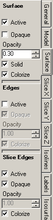
control panel Surface is used to adjust parameters of the surface
visualization and thus has also impact onto results of evaluations related to
the components surface:
Colorizing and Isolines (Isotherms).
The surface, if rendered opaque, will obscure all other evaluations specific to
the objects interior (Isosurface,
Streamlines,
Slices etc.)
The
control panel Surface is used to adjust parameters of the surface
visualization and thus has also impact onto results of evaluations related to
the components surface:
Colorizing and Isolines (Isotherms).
The surface, if rendered opaque, will obscure all other evaluations specific to
the objects interior (Isosurface,
Streamlines,
Slices etc.)
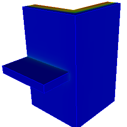
The surface (and eventually its edges) are rendered colorized. Actual colorizing follows values of currently active function (temperature, heat stream density, surface humidity etc. - selected within General control panel) and currently selected Colour table.
| Active, Opaque, Colorize | Decide about the visibility, colorizing and transparency of the surface (and its edges if applicable) |
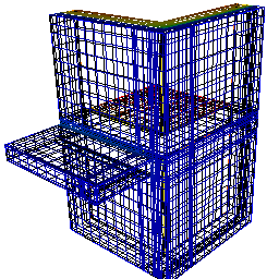
| Solid | When turned off allows the wireframe view onto the fine grid at which temperature distribution and secondary functions are calculated. |
| Edges | Allows emphasizing of component's edges, i.e. lines at
intersections of surface plane elements. Rendering of surface edges can be requested independently of the surface - made visible or transparent. |
| Slice Edges | Allows emphasizing of
slice edges (rendered only if any
slices are active). Rendering of slice edges can be requested independently of the surface - made visible or transparent. |
Remark: The surface displays components hull
coloured by the
primary function (including
adiabatic cut-off planes – so called "wonders", adiabatic planes). The surface is rendered partly transparent (according
to the setting of the
opacity value). To receive an opaque
(non transparent) rendering use the
switch Opaque. The surface can be rendered as a wire
frame (lines) – turn the
switch Solid off – to
display the grid used for evaluation of results.
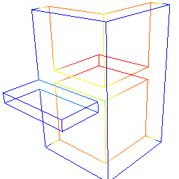
Remark: Construction edges show the position of all
edges of the component. This rendering is useful while the surface itself is not
shown (inactive or transparent). Displaying construction edges might be also
very helpful when verifying the correctness of model input.
Remark: Graphical objects used to render the surface are oriented outside
of components interior. This also ensures proper colouring of the wireframe view
of the fine grid (the
„back side“ of the wire frame is black).
![]()
See also: Results 3D window, Active (setting), Opaque and Opacity (setting), Colorize (setting), Solid or Wireframe (setting), General (control panel), Active function, Isosurface (control panel), Streamlines (control panel), Vectors (HedgeHog, Arrows) (control panel), Isolines / Isotherms (control panel)