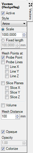
Vectors (HedgeHog, Arrows)  (control panel)
 The
control panel Vectors (HedgeHog) is used to adjust parameters of the vector field
evaluation with arrow symbols.
The
control panel Vectors (HedgeHog) is used to adjust parameters of the vector field
evaluation with arrow symbols.
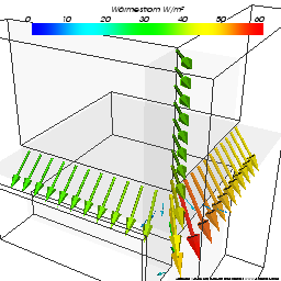
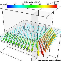
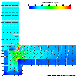
Arrow symbols shows the direction of heat flow through within the construction at any arbitrary point or points on 1,2 or 3-dimensional regular mesh.
![]() If there is
vapour solution available
the flow of vapour diffusion can
be visualized with this evaluation alternatively.
If there is
vapour solution available
the flow of vapour diffusion can
be visualized with this evaluation alternatively.
The evaluation is performed over the calculated field of heat flux vectors (or vapour diffusion flux vectors) at all nodes of the simulation grid – these fields are available only if evaluation of secondary functions has been chosen (in General the secondary functions is active!). If there is no vector field data available to render the tab will show a tooltip stating that.
Vector glyphs will be calculated over the active vector field. Vectors (which direction and eventually size independently from the active function always follow the active vector field) are shown colorized. Only the colorizing of vector glyphs corresponds to the active function (temperature, heat flux etc.) as set in the General control panel and depends on the colour table selected.
The length (and thickness too) of arrow glyphs follow the magnitude (vector norm) the active vector field (Scale) or are shown at fix constant size.
Alternatively to showing arrow glyphs cone symbols or lines can be chosen.
Arrows at one probe point (Slice X/Y/Z) or Mesh Points
The position of the point to display the arrow glyph is defined by the intersection of the three slice planes Slice-X / Slice-Y / Slice-Z.
Therefore the slices X,Y,Z provide crucial part of parameters required for this evaluation (but need not be active nor visible).
Starting from that probe point a regular mesh of points can be created (at given step, distance) and that either along the Line X,Y or Z, the slice plane X,Y or Z or throughout the whole volume.
| Active, Opaque, Colorize | Decide about the visibility, colorizing and transparency of glyphs |
| Style | The representation of an glyph:
Remark: Rendering details of arrow glyphs are set within application settings. |
| Scale | The size (length) of the glyph shall scale by magnitude
(vector norm) the
active vector field . The
normalized magnitude is then scaled by the factor given. Remark: Scaling the normalized magnitude means, that the maximum value within the vector magnitude field is 1.0. |
| Fixed length | The size (length) of the glyph shall be exactly the value given (in millimetres). |
Mesh points at:
|
The position of vector glyphs is defined either by the
intersection of the three slice planes
Slice-X / Slice-Y / Slice-Z or at a regular mesh of points along the Line
X,Y or Z, the slice plane X,Y or Z or throughout the whole volume.
Remark: The setting "Volume" in combination with too dense mesh might result in display of too much information to be interpreted. |
| Mesh Distance | The name of the space from which the streamlines shall be
drawn Remark: The resulting number of mesh points is limited by following criteria: 500 intervals at each axis direction; total maximum of 100.000 points. |
Remark: When surface humidity is selected as active function (panel General), glyphs are coloured grey only, because the function of surface humidity is defined at component's surface only.
Remark: Because starting points for the glyphs exist within model's interior only it
is advisable to either turn the view of the
component's surface
completely off or show it partially transparent (i.e.
not opaque) or show it as
wireframe only.
The tooltip of the tab will show up if the surface
obscures objects rendered within the interior of the model.
Remark: Glyphs will not be placed within regions of stagnation (flux <10e-17).
See also: Results 3D window, Active (settings), Opaque and Opacity (setting), Colorize (setting), Solid or Wireframe (setting), General (control panel), Active Function, Isolines (Isotherms), Slice X,Y,Z (control panel), Surface (control panel), Streamlines (control panel)