Elements 3D window
The Elements 3D window shows a 3D view of the component entered. This view is used for continuous verification of the input and of the resulting construction model.
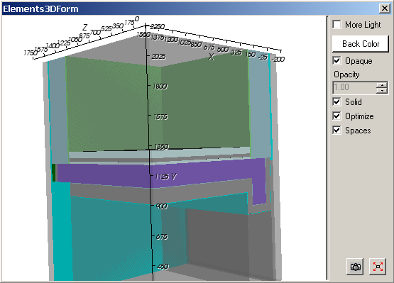
The 3D view can be arbitrarily moved within virtual 3D space with the mouse (rotated, translated or zoomed). The 3D view can be copied onto the clipboard to be pasted later into another application (e.g. Word) from the clipboard - for example for the purpose of integrating this 3D view into some user's report.
| More Light | If checked is turns additional "light sources" on to add
more contrast or brightness to the view. Remark: Adding more light might result in perception of some shift of how the view coloured - this might be sometimes confusing the the viewer with "overexposure". See also: More Light (setting) |
|
Back Colour |
Allow for the choice of the background colour used in the
3D view. See also: Background colour (setting) |
|
Opaque, Opacity |
Defines the
transparency of model surfaces.
AN opaque object is obscure. It obscures fully all objects located behind it.
It the opaque checkmark is removed, the opacity can be set to define the
degree of transparency of the object. See also: Opaque and Opacity (setting) |
| Solid | Changing this setting allows for the choice if objects are
shown as solid models or as wire frame (lines) only. See also: Solid or wireframe (setting) |
| Optimize | Coinciding ashlars of the model resulting from overlapping
elements (minimum grid) are analysed for equal properties and joined into
one object if possible. Remark: Turning this setting on is especially useful to eliminate most of partly transparent planes nested within space areas which might be distracting for the observer. |
| Spaces | Displaying of space elements (space boxes, shown partly
transparent) can be turned on or off. |
|
|
The Position and scaling of the view will be adjusted to
show the whole component within the window. |
|
|
The image of the 3D view is
copied onto the
clipboard.
The 3D view can be copied onto the clipboard to be pasted later into another application (e.g. Word) from the clipboard - for example for the purpose of integrating this 3D view into some user's report. |
The View
The view shows the model resulting from the overlapping of all elements entered within the component (this is the starting point of so called "minimum grid").
How each element is shown depends on element's type and colour assigned to is, whereas:
- Empty boxes are only visible if selected
- Space boxes are shown partly transparent.
Element(s) currently selected in the element list are shown emphasized by their edge lines.
Remark: When this window is focused following functions specific to this window are available from the main menu:
- View→3D Navigation functions (side views, rotations, perspective etc.)
- Edit→Copy to place the Image on to the clipboard
- File→Export→Image... to save the image to picture file
- File→Export→Scene... to save the 3D scene to 3D scene file.
Remark: Labels on axes can be adjusted within application settings.
Remark: The size and proportions of the picture placed onto the clipboard are preset within application settings.
Remark: Current position of the 3D view (the isometry given by the current view vector) will be retained when the window is closed and saved when the application exits. The next time the window is opened the view isometry will be restored if such behaviour is set within application settings.
See also: Elements 2D window, Element Editor, Element selection window, Further control elements, 3D Navigation in 3D windows, TrackBall rotation, The main menu, Coordinate system, Application settings