Completing the Model in Three Dimensions
The construction will be built up by copying and editing component layers in succession.
Starting with layer 1, floor/wall section, displayed as illustrated above (use view menu), right-click over the Layer Browser to reveal its context menu and select Duplicate.
The geometric and material data of all the elements in layer 1 is hereby copied into the currently displayed second layer.
Now edit the name and thickness of this layer by moving the cursor to the name field (press TAB):
Layer 2: Floor/stucco Depth.:1
The section through the stucco (layer 2 of the model) is simpler than the previous one, i.e. composed of fewer material elements. The first stage of editing is to page to those copied elements which are not needed for this section and simply delete them, one by one.
Now display and then delete both "exterior plaster" elements from the elements list within the second layer - these are originally listed in Element Browser at positions 6 and 10.
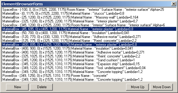
| element # | material |
| 10 | ext. plaster |
| 6 | ext. plaster |
Select the Element by clicking on it and press Delete command button. Delete only those two elements!
The second stage of component group editing is to make any necessary adjustments in the input values of the remaining elements.
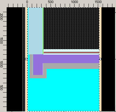
For this layer of the model, only the size of one element needs to be changed. Select element 2 - stucco and by double clicking on it open Element Editor, move the cursor to input of Y_1 (using TAB key), and enter:
X_1:    0
X_2: 1525
Y_1:    0
Y_2: 2200
Press TAB to confirm the change and re-draw the component. It should look like this:
Now the same copy and editing procedure shall be repeated to establish the next layer of the model, component layer 3:
- Right-click the second layer within the Layer Browser and select Duplicate.
- and provide input:
Layer 3: Exp.strip layer Depth.:4
- Within Element Browser form delete following elements:
| element # | material |
| 17 | concrete topping |
| 16 | heat source over concrete topping |
| 15 | concrete topping |
| 14 | isol. underlayment |
| 10 | adhesive mortar |
| 9 | insulation |
| 8 | reinf. concrete |
| 7 | adhesive mortar |
| 6 | insulation |
- Edit element 6 (formerly 11) - reinf. concrete
X_1:  125
X_2: 1525
Y_1: 1025
Y_2: 1200
The cross-section for this and several of the following model layers shows the perimeter brick as well as the insulation along the edge of the floor slab. For this part of the construction, two new elements must be inserted into the component group "under" the element of reinforced concrete.
Select "Reinf. concrete" in Element Browser. Right-Click on it and select "Add→Before Selected". Edit the input Data:
X_1: 85
X_2: 1525
Y_1: 1025
Y_2: 1200
Type: Material Box
Double-Click over the Lambda field to reveal the list of Materials. Select insulation and drag it onto Element Editor - drop it there assigning properties of insulation to the newly create element.
Material Name: insulation
Lambda: 0.041
The new element 6 - insulation - is generated upon confirmation (TAB), and the reinforced concrete element is now number 7.
The perimeter brick element shall be inserted "under" the insulation. Select "insulation" in Element Browser. Right-Click on it and select "Add→Before Selected". Edit the input Data:
X_1:   25
X_2: 1525
Y_1: 1025
Y_2: 1200
Type: Material Box
Material Name: Perimeter brick
Lambda: 0.5
Make sure, that the sequence of elements corresponds to the following (starting from element 5 down here): ??????????????????
| element # | material |
| 5 (space) | int. transfer coeff |
| 6 | perimeter brick |
| 7 | insulation |
| 8 | reinf. concrete |
Layer 3 is now complete. Duplicate that last layer to the fourth now.
The rest of the layers of the demonstration object require editing of copied groups only with respect to name and thickness, followed by a successive deletion of elements:
Layer 4: Int.plaster Depth.:20
Delete following elements:
| element # | material |
| 10 | expansion strip |
| 9 | sand cushion |
| 5 (space) | int. transfer coeff |
Duplicate the last layer to the fifth now.
Layer 5: Masonry layer Thick.:200
Delete:
| element # | material |
| 4 | interior plaster |
- Edit element 3 - Masonry wall
X_1:   25
X_2: 1525
Y_1:    0
Y_2: 2200
Layer 6 (via Duplicate of layer 5):
Layer 6: Slab perim.insul. Thick.:40
Delete:
| element # | material |
| 6 | reinf. concrete |
Layer 7 (via Duplicate of layer 6):
Layer 7: Perimeter brick Thick.:60
Delete:
| element # | material |
| 5 | insulation |
Layer 8:
Layer 8: Stucco layer Thick.:25
Delete:
| element # | material |
| 4 | perimeter brick |
| 3 | masonry |
Layer 9:
Layer 9: Ext.space Thick.:100
Delete:
| element # | material |
| 2 | stucco |
The construction is now complete; the eight component layers can be paged through using the Layer Browser. Save the model data as a construction file in the usual manner:
File→Save
For model documentation, use the options from View→Evaluation&Reports→Data Entry Report.
> Continue reading with "Evaluation and Output"...